REFLECTANCE
BEYOND PHOTOGRAMMETRY
REFLECTIONS
The reflectance of the object’s surface is its effectiveness in reflecting light. Given that reflectance is a directional property, most surfaces can be divided into those that give specular reflection and those that give diffuse reflection. In classic photogrammetry, we tend to avoid specular reflections. For that are using diffuse lights, overcast days, polarization filters, using IR or UV lights, spraying surfaces with matte sprays, just trying to capture images in a way specular reflections are minimal, etc. One of the most loved by any photogrammetrist objects is dirty, with a lot of dust and rust objects.

They are easier to scan, the diffuse texture becomes perfect and on renders as well as inside real-time apps they look great. But a lot of real-world objects have both diffuse and specular reflections. And even if you’ll capture only a diffuse map and use it only, you just can’t reach realistic results for such an asset later. In some cases, global shader specular reflection settings can work, for some objects, you can paint or recreate specular reflection maps quite easily. But in this chapter, we’ll find a way to capture some of the real object reflectance properties.
Also, we should understand, that maps we can capture in most common photogrammetry or photometric workflows only give raw data with desired material properties we can use for later post-processing. In some cases, captured maps can be used as is, in some will require lot of tuning to have correct results in PBR renderings.
SPECULARITY and ROUGHNESS
There are lots of misunderstandings around these terms in 3d scanning communities. And most common one is mixing Specularity and Glossiness (inverted Roughness). In terms of the physics of lights and materials Roughness is one of the properties of Specular Reflection. Specularity as a material property often not exist in modern shading models that compute Specular reflection components as a function of Roughness, Fresnel, Color, Metallicity, etc.
But for dielectric materials often used shaders that allow define Specularity properties as single property or as two properties: Specularity Intensity and Specularity Color. In that case Specularity define what percent of light will reflected via specular reflection and color filter that have material specular reflection component.

Roughness property give us information how rough or how glossy material. And this is scalar values and as result grayscale map. Often defined in [0.0 ~ 1.0] range where 0.0 roughness mean pure glossy/mirror like material and 1.0 is max roughness. Glossiness is inverted roughness.

If you have some experience in a photography, you probably know that there some way to minimize specular reflections using polarization filters (aka CPL filters). Or you maybe you have sunglasses with polarization filter on them and already know how they are working.
And this is a main and easiest trick that used in capturing material specular properties — using polarization filter to remove or minimize specular component. Captured two images without polarization filter and with filter and difference of these two images will give us some information on Specular Component. And that what 90% of people who using polarization scan setup can capture. This is not a Roughness or not a Glossiness, this is a whole Specular Component.
Most other technics are used similar way — finding difference between captures where material in specific condition have less specular component and condition where material have most of specular component. And again, most of them extracting whole Specular Component only.
Capture Roughness or Glossiness capturing required more advanced setups more data to process and more complicated math on that. It can be estimated as a derivative from surface micro-displacements (Cook-Torrance microfacet shading model) using differential rendering methods. Or using second order spherical harmonics. So, in most cases Roughness can’t be captured so easy and for cheap.
Let’s start from some simple things, from using light polarization to capture Specular Component.

POLARIZATION
Every light on reflection from dielectric material become polarized in angle parallel to surface it was reflected.
In 3D scanning this effect often used to lower reflections on semi-glossy materials. Without polarizing filter specular highlights on scanning surface are “moving” when camera or object changed it orientations. And that can decrease quality on features detection and matching or just add more false positive errors.
Polarization filter block lights that have perpendicular orientation to PL filter and pass lights that have parallel polarization. That effect is not binary. Light that has polarization on some degree to PL filter will lost fraction of its power, more this angle to 90 degree more it will be filtered.

Difference between cross and parallel polarization (or no PL filter) will give us combined Specular Component, that can be used after some tweaks as Specular Map.
Most naïve and simple way that should work well for turntable scans is find PL filter orientation that eliminate as much as possible specular highlights from object and capture two sets of images one with PL filter and another without this filter.


Using live view or doing test shooting find best orientation for CPL filter on lens that will remove as much as possible specular reflections. And all later captures do with this orientation. You can adjust CPL filter orientation on rising or tilting camera on higher or lower turntable loops if needed. Sound may be a bit complicated, but when you become familiar with CPL filters it will require couple of seconds to adjust it if needed.
Drawback of that capturing method that CPL filter that filter cut from 1 to 2EV of light. And you need use higher exposure time or higher ISO with polarizing filter. That probably less usable for handheld scans but should not be a problem when using tripod in turntable scan.
To simplify capture process, it possible do not remove CPL filter for shots with specular component, but just find CPL orientation that have maximum specular reflections. Photos above use this way. On first image with CPL filter in orientation that passing most of specular reflections and second one that cut most. Usually, these orientations have 90-degree difference.
Capture process depend on your own preferences. You can capture whole object with specular reflectionsand repeat this with removed specular components. Or you can capture one loop on turntable scan, rotate CPL filter and repeat capture. Change camera orientation rotate CPL filter to pass specular reflections, capture next loop, rotate CPL to remove reflections and repeat… till you finish scan.
To process that scan in photogrammetry software you will need use all photos from both passes to correctly triangulate camera positions for both captures in alignment step. But for meshing it is ok to disable cameras/images from one of type of captures. In most cases in that moment disabling images with specular reflections.
Such images can give you better mesh rendition than images with lot of specular reflections. But there are always can be a corner cases when other images can work better. For example, dark surfaces or surfaces with pure colors like Red or Blue that without specular reflections can be completely flat and not give any good details for depths and mesh reconstruction.
After finished meshing you need project two textures. One with images with specular reflection and another without. And exporting this textures process specularity map in preferred image processing software.
Better be ready that using single CPL filter is not possible fully eliminate specular component, but it still possible to use this data for specular map.
To correctly separate specular component is better work in 32bit float mode.
Open textures, convert them to 32bit and drag and drop texture without reflections on top of texture made with reflections on.
If we need only grayscale specular map we can skip for this moment color calibration step, that we will discussing later. Only thing we need to do is match exposure of both images. But main trick here that we need to find on textures some pieces that we know have diffuse material. And using that match exposure.
In Photoshop I usually make temporal mask on top layer adding exposure adjustment layer and tweak exposure as needed.

Sometime that can be tricky. And better to have some easily recognizable diffuse material somewhere. Or just use your imagination, if this is just a hobby scan and you have good feelings of shaders.
When we match exposure, we can delete mask and change blending mode to Subtraction. That will subtract information without specular reflection from information with specular reflection and left us only specular reflection component (with some garbage from imperfections of capturing method).

Now just convert image to grayscale and convert to 16bits and do final cleanup and tweaking.

Result it not 100% perfect but can be used as specular (specular albedo?) map in most specular shaders.
Now let’s do real practice. For that we will use plastic candle.
To separate specular reflections component, we will capture two turntable loops. One with different elevation levels with CPL filter on lens oriented that way that we can see most of possible reflections (that was vertical orientation). And another two loops rotated 90 degrees (horizontal) that will hide most of reflections.
Correct orientation you can find rotating filter with live view on camera.

Pre-process RAWs and try match same exposure using pure diffuse material as a reference. Such material should look identical on any CPL filter orientations.
Align all images from both passes, and compute mesh.
I made a quick retopology in zBrush (send me a message if you interesting in zBrush cleanup and retopo techics).
And import clean retopo mesh back to RealityCapture.

Now we need
- disable one orientation images
- texturize
- enable disabled images
- but disable images that was enabled before
- and texturize again.
This will give us two textures, one with diffuse and specular reflections and another with diffuse and “no specular” reflections.

Cylindrical surface on left looks more vivid and darker than right with specular reflections. Top side due to big angle to camera sensor was filtered better on vertical than on horizontal filter orientation.
For that time is better use difference blending mode instead of subtraction. And it gives us something like that.

And depend on your preferred workflow you can convert to grayscale and tweak as you wish. Some prefer to use color Specular maps, some grayscale Specular map.
Probably not the best material in terms of details variations in specular components, and additional sublayers like coatings that add this color washing effects on combined capture, but we can see that even such simple separation with only single CPL filter and almost no studio lights setups still can give us specular component information that we can use.


POLARIZED LIGHT CAPTURE
Using CPL filters always have one biggest disadvantage — it loses precious lights that always not enough for photogrammetry, where we need to work with big aperture numbers to maximize depth of fields. And for better control on capturing process, better diffuse and specular components separation, scanners use polarized lights. Instead of using only CPL filter on lens we will use PL filter on light and CPL filter on lens. That should allow capture almost clean diffuse reflection component without adds of specular reflections on it. Using two captures — one with cross and parallel polarized lights. Cross — is light polarization perpendicular to lens filter orientation should filter most of specular reflections and left only diffuse (albedo plus some shadow information). Parallel — is light polarization and lens filter are parallel and should pass most of reflections (diffuse and specular).
CALIBRATION
When using light filters color calibration become more critical. But do it we need to understand that inks used to print color charts can use pigments producing not only diffuse reflection but also specular reflection. And if we try to use cross polarized light capture, we can’t use provided by color chart manufacturer values that are measured using normal diffuse lights.
We must use parallel polarization capture to measure color cast from lights and lens filters. Because most of lens filters are used glass and coatings with minimal color distortions most of impact is from polarization gel on light.
That parallel polarization capture will be used to build color profile that will be used for both polarizations.
To that we need make a good capture of xRite color chart (or any other color charts you have working) using parallel oriented lens PL filter and light filter. Make sure that you do not underexpose or not overexposed color chart. Make sure that you not captured specular highlights from your flashes you will use in capturing system.
For calibration of camera/lens/filters/lights we only need Parallel and Cross polarized capture, but also better capture color chart without any filters, to use it as a reference for parallel polarized shots.
Capturing cross and parallel can be tricky. Parallel polarized shots can be easily overexposed and can have a lot of specular highlights in case you use ring flash or lights behind your camera. Cross polarized can be underexposed and need some practice to find good light intensity to have good definitions on shadows, but not blow out the whites.
For calibration we must use raw images. Captured images need to be converted to Adobe DNG using Adobe DNG converter, Lightroom, Photoshop or any other tool you prefer.
DCP camera profile can be made in you preferred software that have support for your color chart. Easiest one is Adobe DNG Profile Editor.
Open DNG file, choose desired camera profile in dropdown menu, switch to Chart tab define color chart orientation and compute calibration.
Sometimes it can help to capture color chart from different orientations and with some variations on light power. So, you can check how computed profile applying to those images.


If you are using Photoshop/Lightroom copy result DCP profile into Camera Raw folder and now you can open original RAWs and apply profile, you made.
Using white balance picker set a white point and try to match white squares. This a bit far from scientific approach, but to speedup process for first, draft profiles, we can use achromatic colors on color chart. Looks like they don’t have so many specular reflections and we can assume that they should be more or less identical on both lights.
Later you can tweak your Camera RAW/Lightroom presets with better chosen diffuse objects.
But here what we can have from our capture.

And there is quick test on how this separation can work.

Cross + Grayscale Specular looks not identical to original material, but in some but some renderers can’t work with RGB specular maps. And that maps are the source for future textures anyway.
Now possible save RAW processing presets for Cross and Parallel captures and use it in future works. If you plan to use in same conditions, you can “bake” exposure into your preset. If you can only be sure that you are using same lights/camera/filters combination, but can’t precisely control scanning environment, you probably will need tweak presets per capture. To match exposure levels and probably white balance.
CAPTURE
There are couple of capturing scenarios for polarization captures.
Most flexible is capture in two passes, one with parallel polarization and one with cross polarization.
For turntable scans, sometime can be easier to process two passes for every elevation loop:
- capture loop with cross, rotate filter on lens 90 degree and capture parallel
- Rise and tilt camera, capture parallel loop, rotate filter, and capture cross
- Repeat to finish scan
With two cameras possible set one camera filter to cross and another to parallel and capture two images with a single trigger.
With two lights and single camera, it possible to make a controller that will trigger camera and one of lights alternately.
For multi-camera rigs depend on budget can be used mixed lens PL filter orientations to capture both cross and parallel images as a single shot. But that can require more precise camera layouts to have good coverage for texturing. But that can be only way to do polarization capture with flashlights.
LED based light stage type of systems usually use two sets of lights and using cameras with high fps object can be quickly captured using different lightings. That can give cross and parallel captures for every camera, that open the way to compute materials per camera before meshing. That expensive systems are often used for photometric stereo captures and OLAT.
Do you remember that I recommend capturing color chart without any filters on camera and lights? If using parallel polarization passing all reflections from onject to camera sensor, then using no filters will do the same minus any color cast and power loss that can introduce used filters.
And that can be useful for handheld single camera captures with ring flashes or mobile flashes. We can use lower power to capture same details as with slightly higher power from flash to compensate filters. And that mean we can use our flash battery longer.
So here example of handheld capture of boxing gloves I made with Sony A7RIII camera and Godox AR400.

I captured handheld around 270 images with CPL filter on lens and polarization filter on ring flash. And repeat capture without any filter.
After that I pre-processed RAW images to JPEG files for Geometry folder and 16bit TIFF files using wide gamut ProphotoRGB (RIMM/ROMM) for Texture layer.

Aligned all images altogether. And meshed them altogether too.
Someone who probably had experience with polarization capture probably should disagree on using both captures (cross and parallel) for meshing. When often are using only cross polarized images. But him will be slightly wrong.
There are no strict rules to not use Parallel polarization images for meshing, or strict rules to use only cross polarized images. Sometime, like in case of this RED boxing gloves all details are in specular component! If you will try to use only cross polarization you probably will have almost flat blurred surface from lack of features and microdetails. Another good example is pure black plastic materials. If you will try to scan them with cross polarization you will have nothing. Well, you can try to use 10x stronger flash power… if you light can allow that. But if you have more than one color, for example Black and Red, or Black and White… than only way to capture HDRI and merging it to have all details in lights and in blacks.
So choice of what images better to use for mesh is an open question. Because it depends on captured object. For some materials works better only cross, for some can work only parallel, for some combined captures give a better result.

After mesh was done, I simplified it to 10 million polygons and exported into zBrush and did quick cleanup and retopology. Cleaned only supporting object and garbage polygons inside gloves. But retopology spent a bit more time to make a crazy square UV islands and as best as possible edge flows for quads edges.
That is an old scan, that time I played with some UV technics.

When retopology was done I finalized UV in Blender — “squared” UV islands, unified size of quads on UV and packed UV with UVPackMaster Pro. Import UV map back to zBrush, subdivided mesh and projected details from pre-cleaned raw mesh into this retop. After that export higher subdivision level mesh as an OBJ and import it into RealityCapture for texturing. This is mandatory if we want to minimize texturing issues that can happen if we will try to texturize lowpoly mesh.

And now it possible to texturize our scan. For that we should select one polarization images and disable them from texturing. I’m lazy and used Ctrl+R to disable images completely.

Now I run Texturing using Texture layer as a source for Textures.
When that was done, I disabled used images and enabled images that was disabled before. And repeat Texturing again. At the end I had two textures — one with specular reflections and another one without specular reflections.

Now everything similar to previous chapter. Export textures, open them in preferred image editor and subtract Cross polarized texture from Parallel polarized texture (in my case that was No-Polarized texture).

Results become pretty nice for handheld quick scan that took about 10–15 min to capture. Boxing gloves have not so simple topology and have occlusions, and it give us some inconsistency on final textures. But as I already mentioned that textures are raw source for texturing artists. This is not a final result that can be used right after capture processing.
And there is final result rendered in Marmoset using these textures after some tweaks.

You can find interactive 3D Marmoset viewer on link https://www.artstation.com/artwork/3dL8vD
NO POLARIZED REFLECTANCE CAPTURE
Someone probably already frustrated to hear about all this additional and not so cheap hardware like flashes, filters, etc.
But what if I told you, that you can capture specular component without using any filters or specific lights? Neo …

This is old method that was exist for years in most of photogrammetry tools. RealityCapture, Agisoft Metashapes, 3DF Zephir, all of them have it.
Good thing with polarization captures that you have full control over specular reflections. In some systems you can capture specular with only two images. But as you can see this can required dedicated hardware.
And to be honest, specular component separation is only side effect of original use case for CPL filters — removal of “floating” highlights from captured objects. Because these highlights can degrade quality of capture.
But we are doing photogrammetry, and what photogrammetry is? Did we have one or only two images? We usually have tons of images, and that allow us to use small but powerful trick.
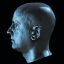
Let’s look into Morpheus “That know more than us…”.
What we see? Can we see glossy materials? Do not count mirror-like glasses. But we clearly can see Fresnel reflection on his head and his jacket.
Another example. Boxing gloves. Did we see specular highlights?

Can anyone who scanned similar objects before telling me how final texture looks from these images? Yes, we did it couple of paragraphs before.

Actually, texture from no polarized images is pretty nice. Photogrammetry software can filter out specular highlights if we have good overlaps between images and texturing algorithm have enough samples from different photos to choose.
But if this work that way, maybe photogrammetry software can preserve highlights instead? Imagine that we have 200–300–400 images that have enough samples to compile texture from clear surface without highlights but also enough samples to compile surface using highlights only.
And this is three cryptical options in Texturing mode: Minimal, Maximal, and Average intensity. And it easier to guess that Minimal can mean that texturing will try to use only darker samples, Maximal will try to use only bright samples and Average will try to use middle intensity samples.


Sound amazing, but biggest issue that these modes almost abandoned by users. So probably only couple of people around the world remember about them. And remember that this mode works EXACTLY as they are named. Max will use ONLY BRIGHTEST samples, Min use ONLY DARKEST samples. Smoothing Blending at all! Only Average looks more as desaturated color map.
Update: On last RealityCapture version they are finally impruved Min/Max texturing mode. Now it much more usable than was before.
And this is one of the reasons that even those people use these methods so rare. Sometimes I can see good combination of specular highlights on raw images, and no way to capture using polarized lights and filters. And in that case, I can try to use this method to extract some specular information from my capture. And that work, not so good, but work. With some artistic skills these textures can be used as a source for specular maps.


That’s old screenshots from model captured using that technic. I scanned boxing glove first without polarization filters. And tested specular map using that method. But wasn’t happy with final results so reshot everything with cross polarization, that definitely giving much clear results.


As you can see, white color work not so well with this capture. And to make capture fairer, it better subtract Average map from Maximal intensity.

In comparison with polarization capture and with that blending issues that have probably all photogrammetry tools this method looks not so attractive. But you always can think how improve it. Friend of mine Eric Christensen already got promising results with improving this technic.
But I’m too lazy with light-stage type systems we have in our studio. But occasionally can use this trick when scanning in time limited situations.
AND BEYOUND: ROUGHNESS
After writing of this article was done I got interesting progress in better understanding of roughness/glossiness properties. And after some more real projects tests, I planning to write next chapter. But that time it will be a lot more math and coding. But this should be a good example of how RawGL and GLSL shaders can be useful with such computations.
Stay tuned, and see you soon
© 2022 Vladlen Erium