PHOTOMETRIC STEREO
BEYOND PHOTOGRAMMETRY
Chapter 1
In one moment of time, when you’ll rich maximum possible for photogrammetry level of details and already own high res camera you’ll have two choices: go deeper to macro scanning using macro lenses, as result increase image count couple of times and hit to physical limitations of optics. Or will try to use photometric stereo technique to capture microdetails normals. This technique can allow to capture details with pixel level resolution. And this part of book is about this.
Photometric stereo is a technique in computer vision for estimating the surface normals of objects by capturing that object under different lighting orientations. It is based on the fact that the amount of light reflected by a surface is dependent on the orientation of the surface in relation to the light source and the observer. In our case observer is a camera.

Most people probably already have seen this definition and that image from Wikipedia (https://en.wikipedia.org/wiki/Photometric_stereo)
But for some 3D artists or scanners that may be still do not give an idea how this working. How actually we can use lights to estimate normals?
For that let’s see inversed process.
For example, Boxing Glove scan. Left picture in first row is a matcap render, right one is common way to visualize surface normals. Last three images are R, G and B images is a just normals render split to separate channels.

Need more hints? Let’s check how this looks in grayscale.

Looks familiar?
R looks like white glove illuminated from right, G like illuminated from Top and B like illuminated from behind camera!
And in photometric stereo capture we just do same but with real object and real lights!
Chapter 2
Someone smart can guess that using only one direction in X, Y or Z can make self-shadows from object topology. And that is correct. So, to avoid this we can use “Plus” and “Minus” “Lights”! And that make even more sense if we will remember that normals and their vectors are encoded using [-1.0 ~ +1.0] range. And if you already know that glove normals render encode those -1 to +1 vectors into [0.0–1.0] range (0% to 100%).
As result Minus values encoded in [0.0 ~ 0.5] range but Plus values encoded in [0.5 ~ 1.0] range.
Let’s “split” one more time our X, Y, Z to “plus” and “minus” views.

As we see now that we can “Illuminate” +X oriented surfaces with light from Right, -X oriented surfaceswith light from Left, +Y with light from Top, etc.
Enough theory. Let’s do some real-world experiments!
Please consider that I only briefly explaining capture method idea, using a lot of simplifications. But this will work, and work for you right now! May be not a perfect, but you can feel a taste of photometric stereo capture!
Let’s start from 5x light orientations. -X +X -Y +Y +Z.


First, we need convert RGB images to Intensity (Grayscale).
Now we need convert intensity to vectors representation. And for that we should blow some dust from our knowledge how vectors are encoding in 3D.
Normals and Vectors
In 3D normals encoded using XYZ basis and vectors always have length equal 1.0 because with normals we encode only polygon or vertex orientation. So, length is not used. Most of apps automatically normalizing normals vectors length to 1.0. But to easier and correct encoding results to image better stay in [0.0~1.0] (0%~100%) range of RGB values. So, our goal also will be normalized normals image.
X-basis encoding using R channel, Y-basis encoding using G channel and Z-basis encoding using R-channel.
Photometric stereo work with object/world/camera space normals. That are different from more common tangent space normals. But as soon as we do not have any mesh and work directly with images, we can only work with this normals.
We need some vector math here. Do not worry. Only some basics to understand used magic. To define vector, we should define 3 float values. For example, vector that looks Right, slightly top and toward the camera can have such values (2.0, 1.0, 1.25)

as soon as length (or magnitude) of that vector for normals always equal 1.0 normalized vector will be (0.78072, 0.39036, 0.48795) that we can encode as float point signed RGB: R 78.1% G 39.1% B 48.7% (signed in case our vector will have minus values). Or if we want to encode it to integer 8/16bit image we need normalize it to [0.0~1.0] range and it will be encoded as R 89% G69.5% B74.4%

And now one of the most important things for us. Any vector in XZY basis coordinates is a sum of three basis vectors X, Y and Z.
What this mean for us? Let’s see again how we can encode X vector in RGB.
X vector can be from -1 to +1. But for simplicity let’s work with +X vector (1.0, 0.0, 0.0). In RGB this vector is 100% R 0% G 0% B.
Do you remember that actual 3D vectors are a sum of their X, Y, Z scalar values that can be represented as lengths or magnitude of basis vectors?
Let’s multiply Pure Red color to our Intensity — grayscale image of +X illuminated sneaker.

+Y is (0.0, 1.0, 0.0) is R0% G100% B0%, just a pure Green color. +Z is (0.0, 0.0, 1.0) — pure Blue color. Let’s multiply +Y and +Z images.


This is simple and you can do that almost any image processing app. I’ll show how this can be made in Photoshop as a proof how simple process is.
IMPORTANT: Photoshop by default work with integer 8/16bit RGB images as with sRGB images with sRGB gamma transfer function applied. As result every conversion between 8/16bit and 32bit in photoshop are going with applying forward or inverse gamma transfer function. But as soon as we are working with linear intensity, this conversion is bad for us. So, we need prepare Photoshop to work with imported images in linear color space. For that we will create custom RGB settings and will use them in our process.
To that we will use standard sRGB color profile:

And chose RGB > Custom RGB

Change Gamma from 2.2 to 1.0, rename to Linear sRGB, press OK and Save.
Now every image will open as Linear sRGB.
PLESE CHANGE THIS SETTINGS BACK TO STANDARD WHEN YOU NEED WORK IN STANDARD MODE!
Next, we just need sum these 3 images. We can use Linear Dodge (Add) blending mode.


Looks not so sexy yet. But now do same with Minus vectors. But from that moment we will work in “Darkness” because no way to display negative colors.
To work with negative values in images we will need to use 32bit mode.
Open next -X and -Y images. And convert them to grayscale as before. Now change 8 or 16bit to 32bit mode, that allow us to use negative values.
Now we need make -X (-1.0, 0.0, 0.0) color. We can’t do this straight forward because color picker in Photoshop can’t do that, so we will use some “math”: — Red is a Black minus Red.
Add black color layer RGB = 0.0, add Red color layer R = 100% GB = 0% and change blending mode to Subtraction. That we will use that as background layer and our Intensity/Grayscale image in Multiply blending mode on top of this. That will give us image with -X component full of different magnitude.
Same we will do with -Y image. But we will need make -Y (0.0, -1.0, 0.0) color. And we will do it from Black minus Green color and multiply to Intercity from grayscale image.

Now we can go back to image with three +X +Y +Z layers. But first we need convert it to 32bit. I prefer to not merge layers in that moment.
And now drag and drop -X and -Z flatten images to project with other vectors. And change blending mode to Linear Dodge (Add) blending mode.

Probably someone already seen such overburned colors when work with normals, for example in Blender when you try to visualize raw normals. But this only because display can’t show negative values correctly.
If we will normalize image to [0.0~1.0] range it looks more as common normals maps. Here I just offset [-1, +1] range to [0, +2] and divide by 2 using Exposure -1.

Now we can flatten image and convert to 16 or 8 bit back but only using Exposure/Gamma option in 32bit to lower bit conversion with default values. And can normalize vectors lengths using xNormal Photoshop plugin.

But do not rush. Even if results already usable but not as good as after we will add 45-degree illuminations.
Method is straight forward; we even do not need to worry about normalized vectors for now. Let’s work with top left, top right, bottom left and bottom right illumination.


Sorry, again some math of school level with plus and minus operations ;)
Top Left illumination give us vector (-1.0, 1.0, 0.0):
Black color layer minus Red color layer plus Green color layer
Top Right illumination give us vector (1.0, 1.0, 0.0):
Yellow color layer (Red 100% G 100% B 0%)
Bottom Left is (-1.0, -1.0, 0.0):
Black color Layer minus Yellow color Layer
Bottom Right is (1.0, -1.0, 0.0):
Black color layer minus Green color layer plus Red color layer

No let’s repeat same as we did for XYZ vectors. And add these layers to 32bit compilation we did before. But this time changing opacity from 100% to 70% on all this TR TL BR BL layers. We will use 70% opacity to “normalize” TR TB BR BL vector lengths because normalized (1.0, 1.0, 0.0) vector is about (0.70, 0.70, 0.0) and we can “scale” vectors globally by that.
Results become looks like that.

See that now we can have values that fall out of [-1.0 +1.0] range!?
Don’t worry. We have good uniform distribution of light directions, and lengths of result vectors can be normalized later. And to normalize normals vectors inside Photoshop we first need convert image to 16bit (or 8bit but better avoid 8bit precision on that steps). But in this modes Photoshop only support [0.0 ~ 1.0] range.
To do this we lower exposure by -2EV and Offset values by adding 0.5 to them. This will give us normalized to [0.0~1.0] colors.

Now we can flatten and convert to 16bit using these options in 32bit to 16bit conversion dialog.

And run Filter > xNormal > xN Normalize normal map

that will give us something like this if we look result with on sRGB monitor with gamma transform.

As soon as we work from 8bit jpegs and did a lot of approximations results not as good as they can be if we will work with 16bit linear images and will better control lighting. But even this image can give you some good sense of Image Based Photometric Stereo Normals.

How we can improve this results?
Well, we completely ignored Z-vectors. But actual light orientations had Z component everywhere.
Let’s add on our 32bit compilation pure Blue color R0% G0% B100% add it on top of all layers (but behind Exposure layers) Set this layer to Linear Dodge (Add) mode and change opacity to something like 35%…

Flatten, convert to 16bit and normalize in xNormal plugin again.

Now we will have a bit better look (in sRGB)

Chapter 3
After publishing first two chapters I found that I can slightly confuse people with quality of photometric stereo results in this workflow. And they are correct about their thoughts. What I show and how use this is not too precise to use to Shape Reconstruction. The classical photometric stereo problem concerns itself only with Lambertian surfaces, with perfectly diffuse reflection. And required known precise positions of lights to solve equitation correctly. But the way how I «salt to taste» blue color, how roughly assume of used light orientations will not make good shape. Difference from classical goal is using computed normals on top of photogrammetry mesh. And as I mentioned before, we just try to capture all microdetails visible on images. And for that such rough way is totally usable.
Black Orb
Classical photometric stereo required known positions of lights. In previous chapter we roughly assumed lights orientations. With fixed scanning rig its possible measure lights directions using DIY tools and trigonometry.
But there is one easy way to measure light vectors and it dumb simple and almost not required any math knowledge. Using small black reflective ball to capture specular reflection from light.

But how we can get light angle from this sphere? Use even more deeper trigonometry math?

No, we are too lazy for this. And we will use simple trick that will give us exact information we can use directly in almost any image processing app!
For that we will use same blending trick as we used before. Multiplication. We will multiply black orb with…

Do you remember that normals encoded in [0.0~1.0] range as [0.0~0.5] values encode [-1.0~0.0] values and [0.5~1.0] encode [0.0~1.0] values? So, if we multiply this “normals” orb with black orb (or black orb with normals orb) and specular highlight will give us exact value for light angle.


For that chapter we will use synthetic dataset I made from high resolution photogrammetry scan. It has good microdetails, so I rendered it to simulate photometric capture with black reflective balls.


Full dataset in jpegs in attachment. Full resolution datasets for this article I plan to upload later.
Open image in Photoshop drag-and-drop Normals Orb image into it and scale it to fit to black orb. You can distort normal probe to better fitting, but this is not too critical for our use.

In case of black orb in shadow, we can use second one.
Now using Info palette in 32bit mode and Eyedropper tool in 3x3 pixels mode sample highlight color values for all images.

In most cases better use 16bit images and same as before in linear sRGB, because we are working with vectors, not with colors.
- Create small size 160x128px 16bit Linear sRGB image.
- Arrange Photoshop windows to two up vertical layout, set rectangular marque tool to fixed 32x32px size select first 32x32px on top left corner of this image press Shift Delete to pop-up Fill dialogue, choose Color and pick highlight color from image with black orb and normals. Offset marque 32px right and repeat with next image. At the end I’ll have image like this.

Gradient in right corner added for debugging, and not a mandatory.
- After that just run Normalize Normal map xNormal Photoshop plugin.

There is no xNormal for MacOS. But we can use Blender to normalize vectors:
- Creating Plane with Emission shader.
- Original vectors chart loading as Non-Color texture (Closest and Extend).
- Passing to Normal Map Node at World space that normalize input vectors from original texture to 1.0 length and encode to [-1.0,+1.0] range.
- Two Vector Math nodes that divide values by 2 and add 0.5. That encode values to [0.0,+1.0] range.
- Add new texture 160x128px size and float 32bit
- And bake Emission only using Cycles render. Select new texture node to bake into it when you press Bake button.
- Color settings should set as None and Standard.

- And save result as 16bit PNG or 32bit EXR if you wish.
Now work with scan images:
- Convert images to intensity (grayscale).
- Convert image to 32bit (this is mandatory!).
In that time let’s cut some garbage and trying to minimize impact from object self-shadows. For that clamp shadows and lights.
For example using Levels dialogue: Shadows Input Level 30, Highlights Input Level 230.

- Add empty layer, using Color Picker tool set foreground color to color from normalized vectors chart image.
- Fill with this empty layer with foreground color.
- Image Adjustment / Exposure: Offset -0.5
- Image Adjustment / Exposure: Exposure +1.0
- Change blending mode to this color layer to Multiply if it was not set before
- Merge or Flatten image.
After that every image encoded vectors, that we got from black orb highlight multiplied by length of this vectors that we got from light source for this orientation. You can check this by normalizing vectors on any image, this will give pure color, because vectors different in their length but have identical direction.
Normalization of vectors in vector chart we made is mandatory to have better normal map. And in this capture method, better have uniform distribution of light orientations to avoid using weightings for light directions.
- Now, do as we did before. Shift and drag all images to one image.
- Change blending mode for all layers to Linear Dodge (Add).
When we scan almost flat surfaces we can ignore Z-channel and fact that we don’t have -Z lights, but if we work with such thick 3D shape object better compensate this situation. In this example lights were at 5º, 50º and 90º to Z axis. Sum of all vectors will “bend” result vectors too much toward Z axis.

So, we will divide Z component (Blue channel) at least by 2 to have something like this.

- To do this add Exposure Layer, disable R, G in blending settings. And change Exposure to -1.

- Now we can flatten layers.
In this time, we are working with 17 images that can have values near 1.0, and sum of intensities in that step can be up to 17.0. If we want use xNormal plugin that work only in 16bit, first we need normalize values it back to [-1,+1] range. As soon as total intensity in this example should not be so high, and we can use Exposure compensation and set it to -4EV, this will divide all values by 16. This should work better in case we will use xNormal normalize plugin, that required 16bit integer images. Photometric stereo can capture too small intensities and sum of vectors and normalization to [0.0,+1.0] range can give too small values or too small differences that 15bit precision will lost too much information.
To use xNormal normalize plugin we need normalize encoding from [-1.0,+1.0] to [0.0,+1.0] range and switch to 16bit:
- As before using Exposure adjustment twice. First dividing values by 2: Exposure -1EV.
- Second add 0.5: Offset +0.5.
- Next change to 16bit mode choosing Exposure/Gamma mode with 0.0/1.0 default values to avoid any gamma corrections.
Now just run And run Filter > xNormal > xN Normalize normal map
Or we can save original 32 bit image as an EXR and normalize in Blender as before:

And at the end you should have something like this.

Or that

Chapter 4
I bet a lot of people reading first chapters have feelings that photometric stereo in the way it explained in this article is only usable for texture scanning. Because we never discussed about meshes. And probably will be right. Such simple technics are better use to capture textures, may be using Substance Designer, Unity Artengine or xNormal. But if you really want reconstruct mesh (shape) there are some methods you can find on web or GitHub. They use some workarounds to integrate normals vectors to depth/shape. But this math already too complicated to explain so easy.
Is this mean we can’t work with meshes at all? No! As I mentioned before in our workflow, we are combining photogrammetry with photometric stereo. This combination allows us to use much simpler tricks and have good results. And this chapter is about this.
3D Photometric stereo
In this step we will do photogrammetry, but in every camera position we will capture additional photometric stereo light orientation shots. Three directions X Y and Z using sixth shots +X -X +Y -Y +Z -Z for every camera position.
Why not more? Be honest, more is better, but this increases total image count, disk space and processing time as well. For average 24Mpx sensors RAW image is around 30Mb, minimal turntable scan loop is 18 positions, 24 is more robust. 24x6 already give us 144 images. But average good turntable scan is not less than 90+ images. That already give us 540 images we need to work with. 540x 30Mb already more than 10Gb of disk space in RAWs. But we need process RAWs, and this can easily add 50–100Gb more. That’s why in 3D photometric stereo we should use minimal possible light orientations.
There is another synthetic dataset will be used in that chapter. High resolution garden clay figurine photogrammetry scan.

Processing Photometric part
Combine all directional lights for every camera to normals.
Per camera normals end-up like this.

Processing Photogrammetry part
For align and mesh let’s use Front light images (Z plus, ZP).
- Make folder _geometry and move all 15x ZP images into it
- Rename CAT_##_ZP.PNG to CAT_##.PNG remain numbers
- Run RealityCapture and drag and drop _geometry folder into open window.
- When RC ask for HDRI input answer to use originals without conversion.
- Select Images line in 1DS input and press Constant in grouping UI this will Group all images into one Camera/Lens group
- Align, add and adjust Reconstruction Region and Mesh

In next steps we will work with textures, so better do some mesh cleanup and UV.
Texturing
Import this mesh into RealityCapture and texturize from _geometry layer images. This will give use usual diffuse/color texture.
Can we do the same with compiled normals?
To test this let’s create _texture1_photometric folder and move compiled per camera Normals images to it.
Please be careful, image names in Texture Layers (_texture1_photometric folder) should have the same names as images in Geometry Layer (_geometry folder): CAT_01.PNG, CAT_02.PNG, etc. otherwise RealityCapture will not recognize image layers correctly and import them as additional cameras.
- Drag and drop _texture1_photometric folder into open RealityCapture project. In Console view you should see Import 0 images line. But when press to single image on 1DS view you should see additional line with Layer information, and Texture button in 2D viewport option will be active, so you can press it and see imported Texture layer image.
- Now change Texturing settings from Geometry source to Photometric texture source. And run texturing.
Result should be like this

Looks like texturing working, but this texture is not usable at all.

Normal Spaces
Most of 3D artists already familiar with normal maps and know the difference between Color/Diffuse/Albedo maps and Normal maps.
But this is only one from many other types of normals — Tangent Space Normal maps.

Technical 3D artists know that at least two more common normal maps are present: Object Space and World Space normal maps.
Tangent Space normal maps are encoding Surface Normals and required fixed combination of 3D mesh, UV and tangent space normal map.
Object and World space encode surface Normals alone. But this encoding is dependent on chosen basis. In case of World Space basis is related to world XYZ, in case of Object Space basis is related to Object basis itself.
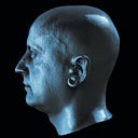
This is how object or world space (if object basis is aligned to world space basis) normals should looks like.


Left is object and it surface normals. When we fly around object it surfaces normals are not changing. Face always face, left ear is always left ear, etc.
We used turntable to “scan” our object because easier rotate object than rotate camera and lights around object!
And as result we captured surface normals like this.

To be honest, there is much more normal spaces. And here we have per Camera Space normals or when we watch these images on screen, we can name them Screen Space normals.
Camera to Global space
And to use this Camera Space normals we need first change their basis from per camera to global one. From Camera/Screen space to Object/World space.
That will allow always have same encoding of surface normals on left ear or tail from every camera position.
Some simple basis transformations or rotation of vectors is possible to use image processing tools like photoshop, but we have camera position every 24 degrees around object, and such rotation is hardly made in photoshop. So, we will use Blender similar as we did before with normalizing maps.
- Create new project (delete camera, light and default cube if it exists in your startup scene)
- Shift+A to add Mesh Plane with same proportions as captured images (for example 0.256m 0.144m for 2560px x 1440px images)
- Select object, in shader editor (you can change timeline window to shader editor) and click Add New material
- Delete Principled BRDF shader node and Shift+A to add Emission shader
- Shift+A add Texture node and load Second image as Non-Color to use pixel values as is
First image we will assume as image with zero rotation against world.
This time let’s use only Vector Math nodes and one Vector Rotation node.

- Multiply Add (A * B + C): Multiplier 2.0, Addend -1.0. To normalize/shift vector encoding from [0.0,+1.0] to [-1.0,+1.0] range.
(X — 0.5) * 2 = X * 2.0–1.0 - Vector Rotate Type Euler
- Multiply Add (A * B + C): Multiplier 0.5, Addend 0.5. To normalize/shift vector encoding from [0.0,+1.0] to [-1.0,+1.0] range
X / 2.0 + 0.5 = X * 0.5 + 0.5 - Add new texture node and Create Empty image with same size as original images, disable alpha and set to 32bit float
- Switch Renderer to Cycles and change Sampling values to something small like 32
- Change Color Management to None, Standard, None and Default Exposure 0.0 and Gamma 1.0
- In Baking options change Bake type to Emit
Now we just need change Y rotation to proper angle and can bake results.
- If First image is zero angle, and capture have 15 images of turntable scan, every camera rotated to 24 degrees against previous position. So, for second image use 24degree, for third 2*24, etc. (N-1) step multiplied to 24.
Depend on left or right rotation his will be plus or minus. In sample scene we need use 24 degree.
So second image Y rotation 24, third 48, etc. - Select empty texture node and press Bake. Usually after baking Image view window should show result, but if it shown, click to Source image and click to Bake texture node again. After that Viewer show result correctly.
- Save as 16bit RGB PNG or TIFF to _texture2_object folder
- Replace source image to next one. Change color from sRGB to Non-Color (annoying but default color space: sRGB)
- Change rotation to (N-1) * 24
- Select Bake texture node, Bake and save result as next file
- Repeat till the end

Now just drag and drop _texture2_object folder to RealityCapture and can use this layer to texturing.
Change Texturing option to use Texture Object layer and Texturize.

Now every side of object have own unique tint. And show that all surface normals probably encoded correctly in world space.
- Export texture
- Open xNormal > Tools > Object/tangent space convertor
- Load our mesh, select smooth normals, select path to Object space normal map, set output tangent space texture etc.
- Press Generate

Result not looks like usual tangent space normal map!
Let’s find where error is
Experienced in 3D scanning and Blender users probably already had some strange feelings in what Y and Zaxises mean.
We used Z axis that look along with the camera and compiled normals as Y up.
In the real world, and applications like photogrammetry or survey that capture or measure real world objects, Z is Up.

And normals we did to texturing object have mixed Y and Z basis.
Let’s open Object and make shader that show object normals.
Geometry input plug to Vector Math Multiply Add node to normalize values to visible range plugged to Emission shader.

As we can see, surfaces have other colors that we had from photometric inputs.

Based on this we can see that for our CAT-01 image Red channel is inverted and Green and Blue channels are swapped.
How that happen?
RealityCapture as photogrammetry app generate mesh as Z-up and mesh normals are encoded using this fact.
There is another pitfall in vector encoding is what coordinate system is, right-handed or left-handed. And that can be a reason for Flipped X normals.
Let’s invert R channel and swap G and B. Anywhere you like.
And try bake tangent space normals one more time from new texture.

Great! Now texture looks almost like tangent space normal maps.

Blue channel looks correct, but Red and Green still looks like some vectors have some rotation against surface normals. And that gave that cyan/magenta shift on different sides of our model.
To find solution we need export model from RealityCapture as FBX with all cams. And open it in preferred 3D software.

First camera instead of 0 degrees have 119.572 degree rotation around Z. And this gives that vectors misalignment!
This can happen because we do not use any Ground Control Points to define real world scale and orientation in photogrammetry app.
RealityCapture SFM module made own decision how object and camera oriented in 3D world space based on camera intrinsic and priors.
There are some ways to fix rotation issue quickly.
First one — rotate Object, bake transformations, export and bake tangent space normal map using this object.
But this will destroy relation with object orientation in RealityCapture scene (or your photogrammetry app).
This is not an issue if you work with small meshes and ready to remember about rotation.
I prefer apply rotation to vectors in object space normal map.
We already rotated X, Y and Z when flipped R and Swapped G and B, and to fix last error we just need rotate our final Object space map to 119.572–90 = 29.572 degree around Z axis.
- Import texture in Blender
- Setup shader on plane object like this:
> Vector Math: Multiply Add 2.0/-1.0
> Vector Rotate: Euler Z 29.572d
> Vector Math: Multiply Add 0.5/0.5
> Emission shader - Empty 32bit texture with same size as original texture
- Select This empty texture and Bake Emit only using Cycles

- Run xNormal and open Tools > Object/tangent space convertor
- Load our mesh, select smooth normals, select fixed object space normal map, set output tangent space texture.
- Set edge padding to zero (you’ll see why, later)

- Press Generate

And now tangent space texture map almost perfect!
Except couple of things:
- Edge padding set to zero and this will give us weird artifacts on rendering.
- Tangent space normal map still holds some macro details that visible as big color differences in some areas.
To eliminate or lower amount of macro details we can use frequency separation technic using High Pass filtering.
Good thing that 3D vectors and RGB values both sharing similar math and High Pass tricks also working with them.
But first download and install Flaming Pear Free Plug-in for Photoshop and install it.
- Open our tangent space normal map
- Load alpha channel as selection
- And do Layer Via Copy to copy only actual texture to a new layer with transparency from alpha we made
- And run Solidify C

- Clone layer
- Run High Pass on top layer with radius enough to define only high frequency — micro details. For example, 64px

In Photoshop you do not really need Solidify before High Pass. Adobe coders was smarter than most of other coders and High Pass on layer with transparency do not create any artifacts (rings) around border pixels. In other apps without Solidify C (convolution pyramid filling), or if we will use Dilate from xNormal or other baking tools High Pass will give strong ringing artifacts around UV islands borders.
- Change blending mode to Overlay
- Select first Solidified layer and add Solid Color adjustment layer on top of it with R 0.5, G 0.5, B 1.0(127,127,255)
- If you do not want completely eliminate low frequency (macro details) you can change fill/opacity from 100% to something like 75~85%

- If you happy with result just flatten, convert back to 16-bit and normalize with xNormal normalize plugin or in Blender.

And test renders in any app. For example, Marmoset Toolbag renders looks as expected.
Enabling normal map do not rotate surface normals and shadows looks identical just with more microdetails on surface.
No visible seams (thanx to Solidify C).


You even can try to integrate normals into micro-displacement map. For example, using Substance Designer or Knald.

And use this map in offline renderers or in zBrush.
Ambient or parasitic light
Let’s talk about ambient or parasitic indirect lite. Someone will probably be worrying that if we use light intensity as direct representation of vectors basis length, then to correctly define vectors they should be captured or preprocessed exactly in [0.0 ~ 1.0] range. Ambient light, parasitic indirect light can affect results?
Technically they can. But in case of 3D photometric capture when we use 6 lights orientations this is not so big issue for process.
Ideal condition when all vectors are captured with intensity from 0 to 1. Red is Plus light vectors and Blue is a minus light vectors

Final computed vector is P minus M.
And in areas where one of intensity is zero, result vector will be P minus Zero or Zero minus M.
But if we have some ambient light or some parasitic indirect illumination (gray vectors), big chance that it will be near identical on Plus and Minus directions.

Final vector in our computation still same P minus M. But in this time P is P + A and M is M + A.
(P + A) — (M + A) is equal to P — M + A — A and equal P — M. So that parasitic light component will be automatically removed when we compute intensity for one basis from two light orientations.
So, can we ignore bad lightings? Better do not. Better lights we have, less parasitic values we capture more valid data we can have.
Just in everything should be balance. If laboratory environment is not reachable, we still can capture good microdetails. Math will help us on that.
Limitations
In first look, photometric stereo looks quite simple and robust. But it has a lot of limitations. And better know them before building your next capture rig.
- First one Photometric stereo in classical approach is limited to Lambertian Surfaces.
But practice just show that in case of combined use with photogrammetry, when we only need to capture micro-details smaller than can capture our photogrammetry hardware, classic photometric stereo with help of lights physics work well with surfaces that have some specular component. Surfaces with not too glossy can still be captured with photometric stereo.
Simple rule — if reflection of light on material do not allow recognize light spot and shape, it probably can be scanned with photometric stereo capture. For example, leather boots can be captured, but lipstick or glasses are not. - Second is a Surface Color.
Monochromatic surfaces, vivid colors, can affect or even made near impossible correct computation of photometric stereo normals. Especially Red, Green or Blue colors. If you need capture something like this, you should think how correctly estimate intensity from these images. - And last but most critical one. Object self-shadows.
If Lights can’t illuminate surface from all directions, computed vectors on those surfaces will have bigger errors.
Like photogrammetry limitation with visibility of surfaces — if surface can’t be seen on different views, depth and mesh from it can’t be computed.
To lower impact of self-shadows can be used more lights together with more advanced photometric technic. For example, light stage type of systems, have less issues, but they cost ways more.
Post Scriptum
Please do not consider this article as an absolute truth. Main purpose of this article to show how simple and elegant photometric stereo idea. And that to start to use it in your own scans do not require any complicated software. Even using Photoshop and Blender it possible to process photometric stereo data.
And if you want to use it more seriously you should investigate more advanced math. Most of photometric stereo algos use Least squares instead of average. Some more advanced lighting technics can give better normals, or just make their capture more consistent.
It also possible to reconstruct depth from photometric stereo. You can search some papers and some code that can do this using “shape from shading”, “shape from photometric stereo” or “depth from photometric stereo”, etc. This methods and code already required some better knowledge in math and coding. Just an open question, how critical lack of photometric stereo depth data if we can capture depth using photogrammetry.
Stay tuned, and see you soon
© 2021 Vlad “Kuzmin” Erium